- 您现在的位置:买卖IC网 > Sheet目录861 > GCM188R71E154KA37D (Murata Electronics North America)CAP CER 0.15UF 25V 10% X7R 0603
�� �
�
�!� Note� ?� Please� read� rating� and� !� CAUTION� (for� storage,� operating,� rating,� soldering,� mounting� and� handling)� in� this� catalog� to� prevent� smoking� and/or� burning,� etc.�
�?� This� catalog� has� only� typical� speci?cations.� Therefore,� please� approve� our� product� speci?cations� or� transact� the� approval� sheet� for� product� speci?cations� before� ordering.�
�C03E.pdf�
�May.17,2013�
�Notice�
�Continued� from� the� preceding� page.�
�3.� Adhesive� Curing�
�1.� Insufficient� curing� of� the� adhesive� can� cause� chips� to�
�disconnect� during� flow� soldering� and� causes� deterioration�
�in� the� insulation� resistance� between� the� outer� electrodes�
�due� to� moisture� absorption.�
�Control� curing� temperature� and� time� in� order� to� prevent�
�insufficient� hardening.�
�4.� Flux� Application�
�1.� An� excessive� amount� of� flux� generates� a� large� quantity� of�
�flux� gas,� which� can� cause� a� deterioration� of� solder� ability,�
�so� apply� flux� thinly� and� evenly� throughout.� (A� foaming�
�system� is� generally� used� for� flow� soldering.)�
�2.� Flux� containing� too� high� a� percentage� of� halide� may�
�cause� corrosion� of� the� outer� electrodes� unless� there� is�
�sufficient� cleaning.� Use� flux� with� a� halide� content� of� 0.1%�
�max.�
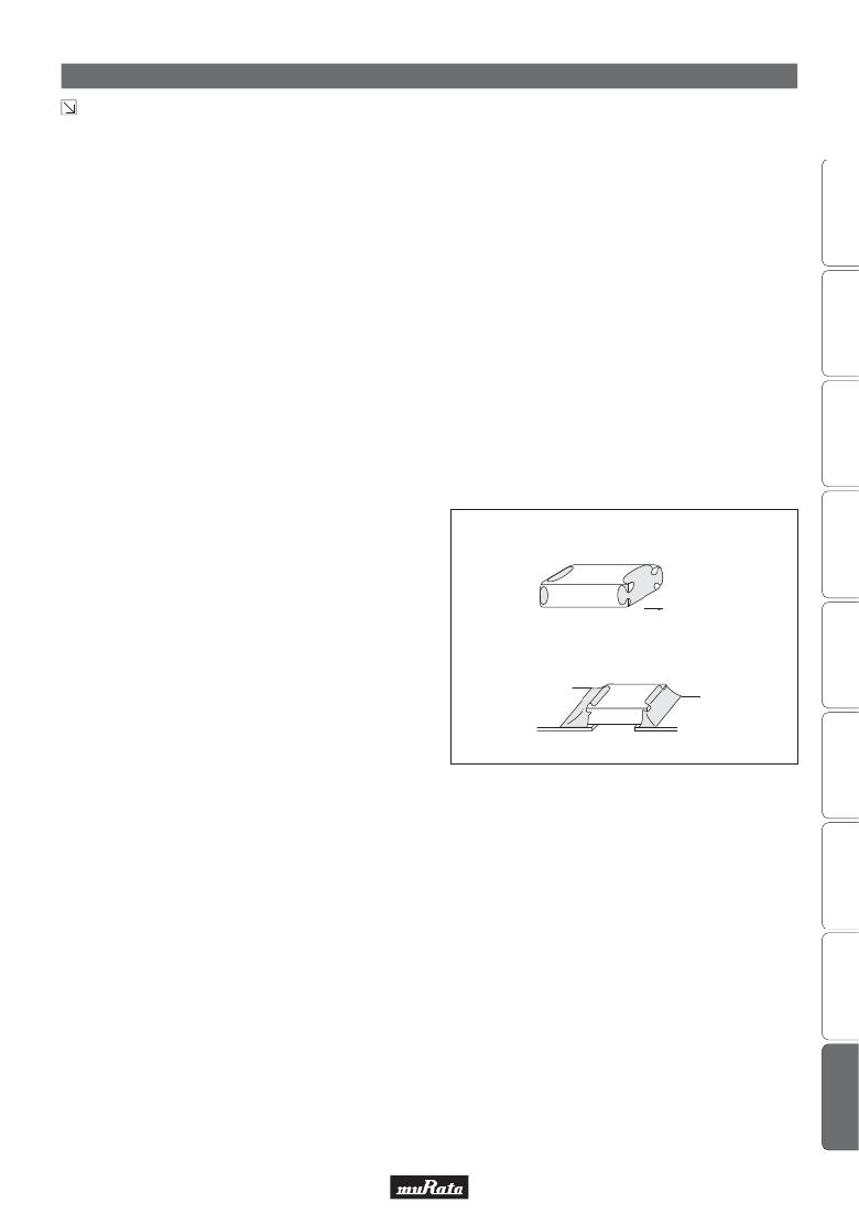
�5.� Flow� Soldering�
�o� Set� temperature� and� time� to� ensure� that� leaching� of� the�
�outer� electrode� does� not� exceed� 25%� of� the� chip� end�
�area� as� a� single� chip� (full� length� of� the� edge� A-B-C-D�
�shown� at� right)� and� 25%� of� the� length� A-B� shown� as�
�mounted� on� substrate.�
�3.� Do� not� use� strong� acidic� flux.�
�4.� Do� not� use� water-soluble� flux.*�
�(*Water-soluble� flux� can� be� defined� as� non-rosin� type� flux�
�including� wash-type� flux� and� non-wash-type� flux.)�
�[As� a� Single� Chip]�
�A�
�B�
�D�
�6.� Washing�
�[As� Mounted� on� Substrate]�
�C�
�A�
�B�
�Outer� Electrode�
�1.� Please� evaluate� the� capacitor� using� actual� cleaning�
�equipment� and� conditions� to� confirm� the� quality,� and�
�select� the� solvent� for� cleaning.�
�2.� Unsuitable� cleaning� solvent� may� leave� residual� flux� or�
�3.� Select� the� proper� cleaning� conditions.�
�3-1.� Improper� cleaning� conditions� (excessive� or�
�insufficient)� may� result� in� deterioration� of� the�
�performance� of� the� capacitors.�
�other� foreign� substances,� causing� deterioration� of�
�electrical� characteristics� and� the� reliability� of� the�
�capacitors.�
�59�
�发布紧急采购,3分钟左右您将得到回复。
相关PDF资料
GCM31A7U2J471JX01D
CAP CER 470PF 630V 5% U2J 1206
GCM31C5C1H104JA16L
CAP CER 0.1UF 50V 5% NP0 1206
GHF459601ZA6N
CAP ARRAY 6CH 600PF 50V 1404
GL2L5LS050D-T1-C
DELAY LINE 0.5NS +-50PS 16SOIC
GL6R0KA7B200
INDUCTOR BROADBAND 6UH
GP447
CAP CER 47PF 1KV 10% RADIAL
GRF4.0419.013.C
GRF4 APPLIANCE INLET FILTER 15A
GRM022R60J332KE19D
CAP CER 3300PF 6.3V X5R 01005
相关代理商/技术参数
GCM188R71E154KA37J
功能描述:多层陶瓷电容器MLCC - SMD/SMT 0.15uF 25Volts X7R 0.1
RoHS:否 制造商:American Technical Ceramics (ATC) 电容:10 pF 容差:1 % 电压额定值:250 V 温度系数/代码:C0G (NP0) 外壳代码 - in:0505 外壳代码 - mm:1414 工作温度范围:- 55 C to + 125 C 产品:Low ESR MLCCs 封装:Reel
GCM188R71E222KA37D
功能描述:多层陶瓷电容器MLCC - SMD/SMT 0.0022uF 25Volts X7R 10%
RoHS:否 制造商:American Technical Ceramics (ATC) 电容:10 pF 容差:1 % 电压额定值:250 V 温度系数/代码:C0G (NP0) 外壳代码 - in:0505 外壳代码 - mm:1414 工作温度范围:- 55 C to + 125 C 产品:Low ESR MLCCs 封装:Reel
GCM188R71E223KA02D
功能描述:多层陶瓷电容器MLCC - SMD/SMT 0603 0.022uF 25volts X7R 10%
RoHS:否 制造商:American Technical Ceramics (ATC) 电容:10 pF 容差:1 % 电压额定值:250 V 温度系数/代码:C0G (NP0) 外壳代码 - in:0505 外壳代码 - mm:1414 工作温度范围:- 55 C to + 125 C 产品:Low ESR MLCCs 封装:Reel
GCM188R71E223KA02J
制造商:Murata Manufacturing Co Ltd 功能描述:
GCM188R71E223KA37D
功能描述:多层陶瓷电容器MLCC - SMD/SMT 0.022uF 25Volts X7R 0.1
RoHS:否 制造商:American Technical Ceramics (ATC) 电容:10 pF 容差:1 % 电压额定值:250 V 温度系数/代码:C0G (NP0) 外壳代码 - in:0505 外壳代码 - mm:1414 工作温度范围:- 55 C to + 125 C 产品:Low ESR MLCCs 封装:Reel
GCM188R71E223KA37J
功能描述:多层陶瓷电容器MLCC - SMD/SMT 0.022uF 25Volts X7R 0.1
RoHS:否 制造商:American Technical Ceramics (ATC) 电容:10 pF 容差:1 % 电压额定值:250 V 温度系数/代码:C0G (NP0) 外壳代码 - in:0505 外壳代码 - mm:1414 工作温度范围:- 55 C to + 125 C 产品:Low ESR MLCCs 封装:Reel
GCM188R71E224K
制造商:MURATA 制造商全称:Murata Manufacturing Co., Ltd. 功能描述:Chip Monolithic Ceramic Capacitor 0603 X7R 0.22μF 25V
GCM188R71E224KA55
制造商:MURATA 制造商全称:Murata Manufacturing Co., Ltd. 功能描述:Chip Monolithic Ceramic Capacitors for Automotive